
The below is a write I just made to document some of the design considerations I used when I put together the control and logic boards for my GP38-2 loco.
Design Concepts for the USA Trains GP38-2 using LocoFi
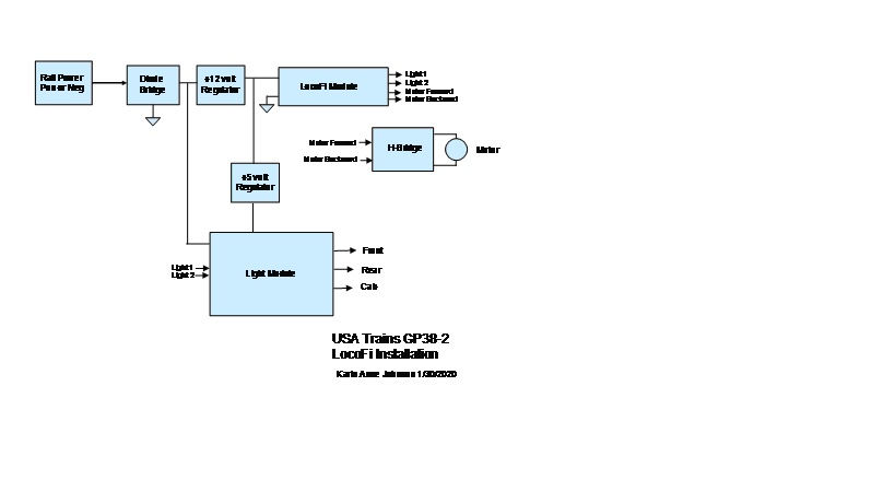
It was desired to use a LocoFi module to control the power applied to the two motors in a USA Trains model GP38-2 locomotive. In addition control of the lights used in this locomotive was also desired. With regard to the lights, the LocoFi module only provides for two light control outputs. The GP38-2 locomotive has front, rear and cab lighting. A method would have to be determined to control more than two lighting features.
From some initial measurements of the motor characteristics in the GP38-2, it was determined that the LocoFi module by itself could not support long term operation of the motors. The GP38-2 has two can type motors installed in the front and rear truck/bogie assemblies. DC measurement of the resistance of each motor indicated about 2 ohms resistance. With instrumentation applied to measure voltage and current applied to the motors, it was determined that approximately 2 to 3 volts DC would be required to just get the motors operating at stall speed. In other words just to get the locomotive moving when on a powered track section. If the voltage was 2 volts then based on Ohms law
E = I x R, the stall current would be 2 amps. The actual voltage required to get the locomotive moving could be higher, as it appears from inspection of the motors, they are at least a four pole or six pole type DC motor. So depending on the position of the rotor inside the motor with respect to the stator assembly, which is a permanent magnet type, it could take upwards of 2 amps of current. Possibly even 4 or 5 amps depending on the motor mechanical load to start it moving. Actual DC current measurements confirmed these assumptions. So the design goal for any motor driver circuit should be able to handle at least 2 amps of starting current, and actually more up to at least 5 amps for safety margins. This assumption would be based upon reliability of the motor driver circuit, as well as thermal management of the devices and physical layout of the electronic components used in the motor driver.
Some comments about motor drivers, and more specifically H-bridge type drivers are needed here. Since we don’t need to “Instantaneously” need to change motor direction, a real H-bridge is not needed here. Research about available off the shelf motor driver devices has produced the existence of a couple of candidates. These devices are not real H-bridge type devices in that they cannot instantaneously switch directions. They are acceptable for use in the proposed application because LocoFi requires the throttle to be returned to zero before allowing direction change. However, these type of devices are limited to about 5 amps of continuous motor drive current. Even with a heat sink applied.
Experimentation would be required to determine if these type of devices would be suitable for use with G Scale motors. Especially in locomotives with more than one motor in the unit.
Two custom designs were developed for this experimentation. One with a motor driver, the other with a real H-bridge type design. The motor driver is limited to 5 amps peak current, while the H-bridge could handle in excess of 10 amps peak current. Both would require heat sinks. More about part numbers later.
The lighting features used in the GP38-2 required a bit of out of the box thinking. Since I wanted control of the cab lighting independently from the front and rear light control of the LocoFi module I had to add a bit of logic to the LocoFi light outputs. The measured current of the lights used in the GP38-2 when using 24 volts DC to power them was about 200 milliamps. Too much for direct transistor control without heat sinks on the transistors. Relays were decided upon for control of the lights, being driven by CMOS logic from the LocoFi light outputs. Since LocoFi has two light outputs, we could define four logic states. OFF, FRONT, REAR, CAB Some surgery on the GP38-2 light wiring had to be accomplished to separate the cab lighting circuit from the rest of the lights. Diode steering is used depending on track power polarity to select the Front or Rear lighting condition in the factory stock GP38-2. At this point I decided that I also wanted to retain the ability to return the modified GP38-2 to factory wiring by using the four bottom mounted slide switches. This was accomplished very easily by the logic added to the new board design for lighting and motor control.
There are three separate circuit boards, plus the LocoFi Module involved in the G Scale
System.
1 – Main base board
2 – Motor driver or H-bridge
3 – Relay/Lighting board
The Motor driver can be replaced with a real H-bridge board capable of up to 10 amps
of drive current. The Motor driver will handle about 4.5 amps. It is an either/or selection not both at the same time. The motor driver board shown is one with the finned heat sink in the middle.

The Main board supports a platform for the two auxiliary boards. It also provides the mount surface for the four control switches to return the wiring circuits to factory stock.
Since the design goal was to support at least 5 to 10 amps of motor current, it was felt that the original stock slide switches would not suffice for reliable performance. This information was taken from the data sheet of the switch manufacturer. Why USA trains decided to use these switches in the first place is beyond me. However, running current for the two motors together is only about 500 milliamps, and in that scenario the switch
Current rating would be fine. It only the prolonged starting current that would potentially cause a problem with reliability. For this reason it was decided to use a high current power relay to route motor voltage from the pickups to the motor driver and ultimately the motors. The Main board also provides connectors for the wiring harness in the GP38-2 which includes the lighting and smoke generator connections.
The Motor Driver board shown in the above picture uses a device made by ONSEMI. Their part number STK681-360. It is not a real H-bridge, although the internal architecture looks a lot like an H-bridge. You cannot instantaneously change motor polarity with this device. And it even states this on the part data sheet. This board can be replaced with a second board design which is a real H-bridge rated for higher current. The pin out of the interface connector allows this interchange.
The Relay/Lighting board contains the CMOS logic for controlling four states from the two lighting outputs from the LocoFi board. It also contains the relays necessary and associated with providing power polarity switching for the Front and Rear lighting boards in the factory stock GP38-2.
The Main base board was designed to fit inside the shell of the GP-38-2, along with the two auxiliary boards.
It has been some time since I have used the system for trials. Since then I have essentially "mothballed" the GP38, and presently am not trying any experiments with LocoFi. The GP38 and all accessories are stored away in a closet. So let me see if I can be of some assistance. My original concept drawing was based upon some very custom hardware that I designed. I never actually finished building the custom H Bridge portion of the hardware design. Instead I used an H bridge I found on the web. It is labeled "XY-15AS". I had to add a couple of interface transistors drive the H bridge with the correct polarity signals. But it does work. There is a video floating around this site somewhere showing the working GP38 with LocoFi. I think it is also on YouTube somewhere too. With regard to the network connections. I don't know which version of LocoFi you are using. I used the very first version hardware board, I don't remember the version number, but probably v1.0 or 1.1. I do remember that there were some issues with early versions of the software being compatible with earlier versions of Android. I seem to remember that version 6 of Android was fairly bullet proof with the LocoFi app. At some point in time my Android phone did an automatic upgrade to version 7 and that seemed to break the functionality of the app. It had difficulty assigning and finding locomotives on the network. That was the last version I tested with. I think , but am not sure there must have been a lot of additional versions of Android rolled out. However I do remember that with version 7 Android I was still able to do a direct connection to LocoFi installed in the GP38. I don't know what has transpired since about a year or two ago. I do remember doing a lot of reverse engineering of the software, and had discussed at one time about getting the software into a "open source" configuration.
But that never happened. At this time you are pushing the "Little Grey Cells" to their limit to further discuss some of my previous efforts. Note: you might tell I am a POIROT fan.
If you would like I can discuss further with direct email. Let me know via this forum and I will give you my direct email. I am not sure this forum would allow that.
Regards,
Karin Anne Johnson P.E.
Palm Harbor, Florida